Discover the Power of Beeptoolkit.

Basic and optional scenarios

Software controllers enable working not only with the main control scenario but also with additional preparatory scenarios. In our latest version, it is possible to add up to nine such scenarios, which can be selectively triggered by the operator either before starting the main algorithm or in conjunction with it. This opens up extensive possibilities for tasks such as:

Automated diagnostics of complex equipment before its activation.
Sensor calibration.
Configuration of external devices.

Additional scenarios can be used to carry out all preliminary steps prior to initiating the main algorithm. For example, before starting the main process, the controller can verify the operability of all system components, adjust sensor parameters, or conduct equipment tests. This helps minimize the likelihood of errors, such as those caused by human factors, during operation.

Flexible adaptation and corporatization

One of the key aspects of software controllers is the ability to store and edit control algorithm instructions in binary format. These instructions, created within an Integrated Development Environment (IDE), can be saved and shared with other users for further use or modification. It is important to note that editing algorithm instructions is only possible within the IDE, preventing unauthorized changes.

How it works:

Algorithms and system parameters are stored in an external binary file.
The file can be quickly uploaded to the controller, allowing the algorithm to run immediately with the specified parameters. You can create dedicated libraries from such files.
Sharing configured algorithm instructions with other users (e.g., colleagues or clients) makes it easy to share settings and solutions, speeding up the implementation process.

As a result, each algorithm can be quickly adapted to specific tasks, and the system can be reconfigured to work with new equipment or altered conditions.

BEEPTOOLKIT is a high-performance two-headed dragon

   Imagine creating automation for your idea – without writing a single line of code!, you simply enter a set of the shortest visual instructions in the world, then connect them to sensors, motors and everything you want to control.

   With the IDE Soft Controller BEEPTOOLKIT you can do it easily, simply and quickly, give free rein to your creativity, turn your ideas into working prototypes or automated systems. Which masterpiece will you create first?

It combines both an IDE (integrated visual development environment) and a freely programmable logic controller based
on a PC (OS Windows).

  • The platform’s logic core is developed in the G language in the environment and compiled into a compact software package. It works with minimal external hardware resources, is easily installed on various computer form factors and supports the initial configuration of USB I/O kits (expandable to 16/16). The current version 025 is supplied as is, ready to use out of the box.
  • The platform runs on a CISC x86 processor and Windows 10…x (LTSC or IoT) OS, providing excellent performance and the necessary external communication interfaces with low power consumption. This ensures efficient data processing, allows the integration of most solutions, including machine vision functions, supports the necessary expansion of input and output channels and facilitates interaction with external devices.

Example of input instructions for the algorithm:

Each port is activated to open an output channel (1–16, switching to logical level “1” = 5 V) with a minimum response time (synchronization) at the hardware level of 70 ms. Repeated activation of the same port with the same instructions closes the output channel (1–16, switching to logical level “0” = 0.4 V) with a minimum response time of 70 ms.

Activation of a channel (1–16) can be performed using an instruction with feedback from input channels. In this case, the output channel (1–16) is specified in the D TRIG field. The input channel(s) (1–16) are activated, as well as the trigger. If the readable value of the trigger exceeds 1 V, the D TRIG channel opens. If this value is below 3.3 V for a given time (e.g., 1 minute), the system proceeds to the next port.

It is possible to create an instruction similar to (2). However, if the event triggering the activation of the output channel (1–16) D TRIG does not occur, the output channel (1–16) in the CH field is activated. The system then transitions to the next procedure for the subsequent port, continuing in this manner until the final instruction for the last port is executed.

BEEPTOOLKIT VP (Vision Pro):
An Enhanced IDE Soft Controller with Machine Vision Functionality
BEEPTOOLKIT VP is an advanced version of the BEEPTOOLKIT Pro platform, equipped with a port for integrating machine vision. This feature enables the use of various types of USB cameras (PTZ, night vision, X-ray, microscopes, telescopes, and others) as sensors for object recognition, significantly expanding the system’s capabilities in automation and robotics tasks.
Key Features
  • Object Analysis: The ability to recognize objects by calculating their color gradients and defining geometric regions based on specified shapes.
  • Flexible Configuration: Users can set parameters for capture speed and duration, as well as perform real-time video capture and data processing.
  • Event-Driven Actions: Upon specific events (e.g., object recognition), one of the 16 output channels can be automatically activated to perform related actions.
Applications

The machine vision port opens up a wide range of possibilities for multi-functional projects:

  • Automation of industrial processes with precise object recognition and control.
  • Implementation in robotic systems for performing spatial analysis tasks.
  • Utilization in scientific research and experiments requiring accurate observation and interaction with objects.
Potential

BEEPTOOLKIT VP offers powerful tools for creating complex scenarios, combining machine vision capabilities with intelligent data processing. This functionality becomes an indispensable asset for engineers, developers, and researchers tackling multi-task projects.


4-16CH 5A Signal Amplifier Board Isolation MOS Module NPN PNP IO Digital Logic Level Converter DC 3.3V 5V 12V 24V

Optocoupler Isolation Voltage Converter  Module. Signal Level Board NPN Output 1.8V 3.3V 5V 12V 24V PNP Output.

PWM Signal Generator Module. Power Input: 8-24V Frequency Signals: 5.4k-160khz,540-16.6khz,80-2.4khz

4-16CH 5A Signal Amplifier Board Isolation MOS Tube Module NPN PNP IO Digital Logic Level Converter DC 3.3V 5V 12V 24V

Load Current:

75A

Load Voltage:

24~380VAC

Control Voltage:

3~32VDC

Control Current:

3~25MA

VCC Voltage: 3.3V, 5V Output load voltage: 0 to 24V Load current: < 5A (more than 1A need to add heat sink)

TB6600 DM542 DM556 DM860 DM860H Driver Cintroller Microstep Motor Brushless Shell For 42/57/86 Nema17 Nema23

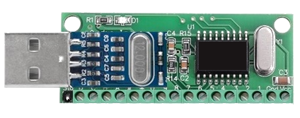
USB Output Interface 16 Channel

The logical core of the platform, in accordance with your control scenario, allows you to configure 16 channels in any sequence logical signals with 2-bit resolution for each output as "0" = 0...0.4 V and "1" = 2.5 ... 5 V (2-bit binary, answer between commands 30-70 ms, permissible load per channel 270 mA). - The module is powered by DC 4.5 - 5V. - All 16 channels are initially pulled to the ground with NPN control. Depending on the complexity of your project, the number of plug-in modules can reach up to 5 with their distribution by ports (16 - 240), which allows you to control up to 80 output channels. * The starter package includes 1 module for 16 channels.

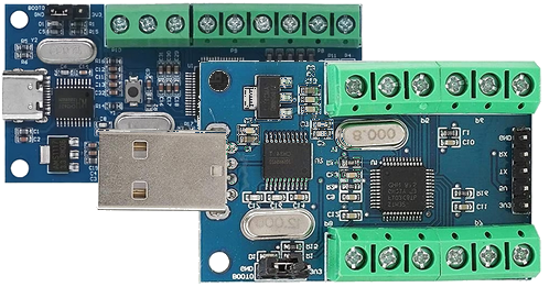
USB 10 and 16-channels ADC sampling modules

We use these great, low cost and commercially available modules as a USB hardware input interface for analog resistive or TTL sensors.

Including 10-channel or 16-channel AD sampling voltage inputs GND: Negative/common ground interface of the sampling voltage.

Up to 12-bit AD acquisition channels (4096 resolution = 0.001 V). Usage: Install the CH340 USB serial chip driver on the PC, connect the module to the PC, IN screw terminals connect to the positive end of the sampling voltage, GND connect to the negative end of the sampling voltage (ie, handling common ground), configure the USB connection ID of the COM ports in relation to the I/O ports of the BEEPTOOLKIT. Baud rate (115200) allows you to see the AD sampling results, the sampling results are updated once every 200 ms.

*The received voltage cannot exceed !3.3V, otherwise there is a risk of chip damage.

** The starter pack includes 1 module for 16 channels and the CH340 driver installation file.

  • SUPPORTED DESIGN.
    Thanks to the TTL I/O compatibility of the platform, the distance between the computer and the USB input module can be up to 10-15 meters (depending on the quality of the connection and environmental conditions), without losing signal integrity, which depends on several factors, including.
  • CABLES & CONNECTORS QUALITY.
    For long connections, it is essential to use high-quality cables and connectors that minimize signal loss and interference.Pollution and electromagnetic interference:
    External interference and noise can significantly degrade the signal quality. When working over long distances, the influence of electromagnetic interference should be taken into account, especially in industrial environmentsWhen dealing with distances greater than 15 m between the I/O GPIO and the sensors, it is recommended to use amplifiers or signal buffers that compensate for the loss of data quality.